Home Page ----- Odyssey Home Page -----Previous Page ----- Next Page
Week Three

Week Three

Continuing the wing assembly.
Positioning the Aileron Control Arms for Final Riveting.

EarthStar provides three alignment gauges that enable you to precisely set the locatins of the aileron contol arms for final riveting.


The Center alignment gauge viewed from the bottom surface.

The Center alignment gauge is loosely bolted between the two center control arms.

It is prenotched to fit around the torque tube. And, it has a notch to precisely locate the top surface of the "D" cell.

Center alignment gauge view from the top surface of the wing.

You have to look closely to see the notch for the top surface of the "D" cell. But, trust us, it is there.

The left aileron alignment gauge.

The right side is similar.

After you insure that your alignment gauges are correct, it's time to drill the rivet holes for the driver arms.

I used a drill long enough to drill all the way through the tube and out the other side of the arm.

Make sure to de-burr the exit hole.

A 1.5 inch hole is drilled in the rear spar and the intermediate aileron push-pull tube is mounted.

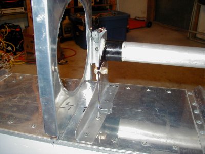
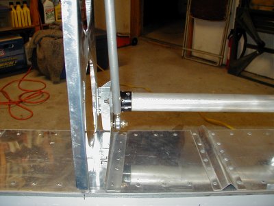
Finally, the hemi-joint is bolted to the aileron driver arm.

Remember, this joint is in it's final position. Take care to mount the washers correctly and properly tighten the nylok nut.

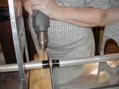
Repeat for the other wing.

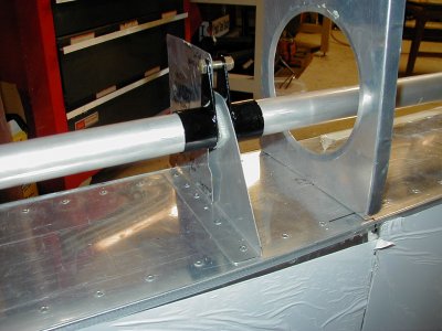
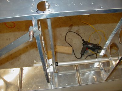
After you remove the alignment gauges, rotate the aileron torque tube to make sure all is free and easy. You'll also notice that Mark has designed in a definite "Ackerman" effect. The up going aileron will travel farther than the down going aileron ... pretty neat, huh.

What is Ackerman effect, you ask?
Take a look here for an illustration: Ackerman Effect

Home Page ----- Odyssey Home Page -----Previous Page ----- Next Page